
Digital Implant Planning with Surgical Guides
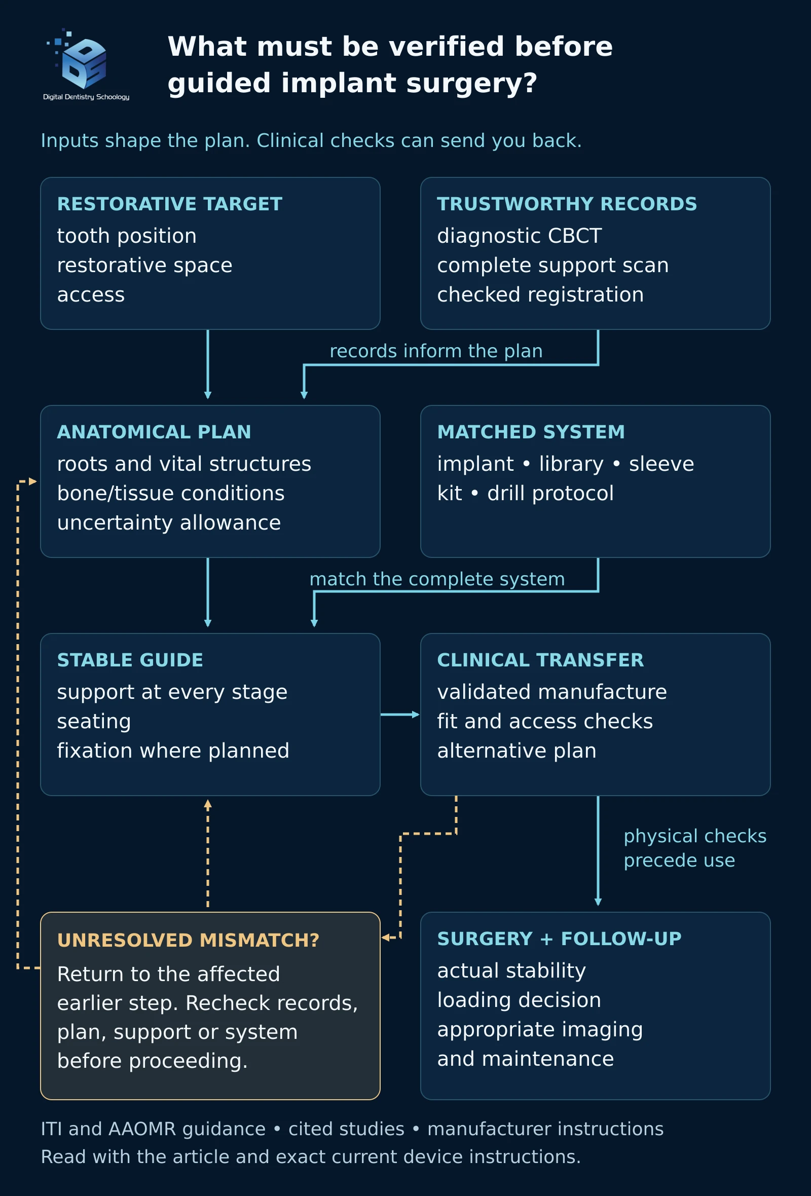
What must be checked before a virtual implant plan can be transferred to the patient with a surgical guide? A useful plan brings together the intended restoration, the available anatomy, a stable guide and a compatible surgical kit. Each needs its own verification. A convincing three-dimensional view does not establish that the guide will seat correctly or that the planned procedure can be completed safely.
This article follows those decisions from records to follow-up. It is a literature-led educational guide for dental professionals; the treating clinician remains responsible for patient selection and the treatment plan. Device-specific steps must follow the current instructions for the exact products being used.
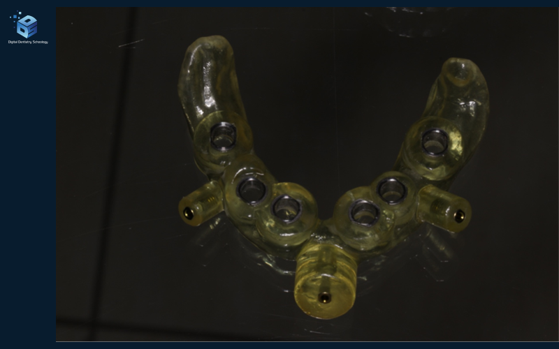
What is a dental implant surgical guide? A physical template transfers a virtually planned implant position to the surgical site. Static guidance uses a fixed template and remains an adjunct to diagnosis and treatment planning, as described by the ITI consensus. The restorative plan, anatomy, guide support and compatible instruments still need verification.
What restoration are you planning?
Before positioning an implant, establish the proposed tooth position and restorative space, then assess whether the anatomy supports that plan. The digital wax-up should inform implant position rather than being added after the implant has been placed virtually. The ITI consensus on computer-guided implant surgery treats guidance as an adjunct to diagnosis and recommends prosthetically driven planning.
Keep three questions separate: Is implant treatment appropriate? Is this implant position suitable? Can this guide and instrument sequence reproduce the position? A favourable answer to one does not resolve the others. The assessment should also establish whether augmentation, an open-flap approach or a different treatment sequence is needed.
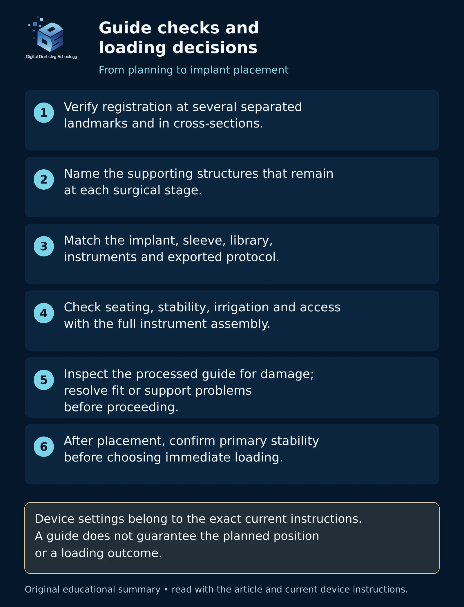
For a proposed immediate restoration, plan a suitable alternative in advance. Guide accuracy cannot establish primary implant stability. The ITI full-arch loading recommendations require confirmation of each implant’s primary stability before immediate loading; implant number and distribution remain prosthodontic and anatomical decisions.
Which records answer the planning question?
CBCT supplies the cross-sectional anatomical information; the surface scan describes the teeth and soft-tissue surfaces used for registration and guide design. The 2026 ADA/AAOMR recommendations recommend CBCT for presurgical implant planning, including static-guide fabrication. Imaging follows clinical assessment and consideration of existing records.
Do not prescribe a full-arch CBCT or a single voxel size for every patient. Select a field of view and exposure protocol sufficient for the actual question and relevant anatomy. The AAOMR implant-imaging position paper explains dose optimization and the need for diagnostic-quality, appropriately interpreted images. A nominal voxel size is not a promise that every boundary is resolved to that dimension.
CBCT also should not be presented as a universally calibrated bone-density test. A 2024 experimental study of implant-planning software found that CBCT-derived HU values were unreliable for that purpose. Interpret anatomy and the clinical situation without treating an arbitrary grey-value display as a validated quantitative bone-quality measurement.
For the surface scan, inspect the intended support surfaces for omissions, distortion and changes since acquisition. The practical question is whether the records describe the anatomy that will actually support the guide, not whether a scanner advertisement reports a small accuracy number.
Does the registration agree in more than one view?
A correctly fitting guide can still direct surgery incorrectly if the surface scan has been registered to the CBCT in the wrong position. Check the superimposition at several spatially separated, identifiable surfaces and in cross-sectional views. If the datasets do not agree, identify the cause before planning further; forcing a best-fit result is not a remedy for unreliable source data.
A clinical study comparing surface and fiducial-marker registration found differences between the approaches and identified metal-restoration artefacts as a concern. Dental surface registration also needs suitable dental references; an edentulous arch cannot simply be treated as a dentate scan with the teeth removed. Choose a supported registration method for that situation and verify its references.
These checks are DDS teaching interpretation of the registration evidence: inspect the alignment where the guide is supported and near the planned implant, document unresolved discrepancies, and obtain corrected records or specialist review when the uncertainty changes the plan.
What does each planning measurement mean?
Review the complete implant and osteotomy envelope against adjacent roots, neurovascular structures, cortical boundaries and the sinus where relevant. Displaying a traced canal does not remove uncertainty in its identification.
The 2018 ITI accuracy consensus recommends a 2 mm safety margin from critical anatomical structures. Treat this as a planning allowance, not a guarantee against injury. The clinician must also account for the actual instruments, guide behaviour and uncertainty in the images. Do not substitute an unsupported universal 1 mm sinus clearance.
Some dimensions are useful when their reference points and scope are retained. Straumann’s planning guidance, for its covered implant lines, recommends at least 1.5 mm from the implant shoulder to an adjacent tooth at bone level and 3 mm between adjacent implant shoulders. These are not centre-to-centre distances or substitutes for examining root inclination and the restorative plan.
Depth requires equally careful language. That document distinguishes the bone-level relationship from the distance to the proposed gingival margin; for its Bone Level implants it describes a shoulder approximately 3–4 mm below the prospective gingival margin in the esthetic region. This does not mean placing every bone-level implant 2–3 mm below the bone crest. Use the selected system’s guidance with the planned restoration and tissue conditions.
For healed sites, the 2023 ITI buccal-bone consensus recommends a buccal bone wall greater than 1.5 mm at placement. Its scope should remain visible: healed sites, with additional hard- and soft-tissue assessment. It is not proof that one thickness prevents recession in every esthetic or immediate-placement case.
Will the planned support still exist during surgery?
Tooth-supported guides rely on remaining teeth; mucosa-supported guides depend on their tissue-bearing fit and planned stabilization; bone-supported guides require surgical access to the supporting bone. The support is part of the surgical sequence, especially when extractions or bone reduction are planned.
A fixed count such as “three or four teeth” does not establish adequate support for every case. In an in-vitro investigation by El Kholy and colleagues, tooth number, location and implant-site configuration affected accuracy. Results from study models do not establish a universal clinical minimum.
For a full-arch extraction plan, identify precisely which teeth support each guide and when they are removed. If all supporting teeth will be extracted, the subsequent guide needs an independently planned support or fixation strategy. Do not label a guide “tooth-supported after extraction” without explaining what remains to support it. This is a design-consistency check, not a substitute for a validated full-arch protocol.
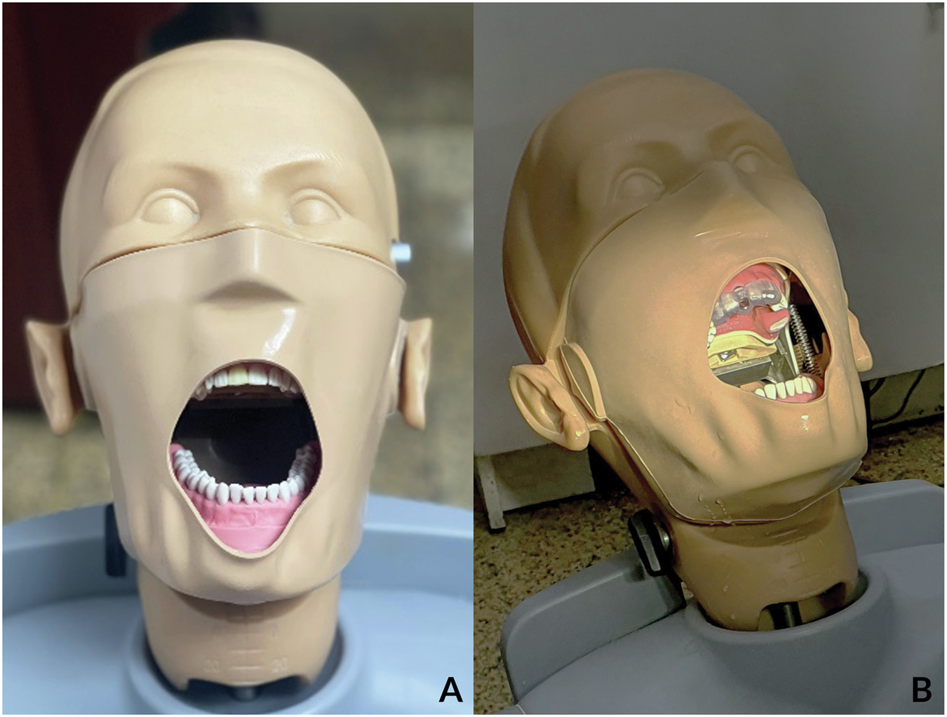
A documented model experiment makes the distinction visible. Nguyen and colleagues used commercial acrylic maxillary models and manufactured guides for use in a phantom-head simulator. The setup illustrates a physical guide on planned support; resin models do not reproduce tissue movement, saliva or variable bone properties. This teaching example concerns the setup, not a recommendation for a universal support configuration.
Does the guide match the complete surgical system?
An implant appearing in software does not prove that its fully guided surgical workflow is available. exocad’s exoplan Library Finder distinguishes implant entries, guidance types, drill protocols, sleeves and fixation components. Verify the exact implant variant, library version, regional availability and surgical kit rather than relying on a brand-level compatibility table.
Before manufacturing, the surgeon and laboratory should reconcile the implant reference, planned position, sleeve reference and position, drill lengths, handles or keys, insertion components and the exported surgical protocol. Any mismatch should be resolved before production.
There is no interchangeable “0–3 mm sleeve offset.” For example, the Straumann Guided Surgery technical guide describes H2, H4 and H6 sleeve positions and their corresponding instruments. It also warns that certain drills extend beyond the implant’s insertion depth. These examples explain why the exact reference geometry matters; they are not settings for other systems.
Plan access with the full instrument assembly and the patient’s mouth opening. Reserve access for irrigation and confirm how seating will be inspected. Sleeve diameter, guide thickness, sleeve housing, relief and inspection openings belong to the compatible design/manufacturing instructions, not a universal dimensions table.
Does the manufactured guide reproduce the plan?
Use a guide material indicated for the intended application with its validated printer, processing and cleaning requirements. A resin’s layer height, a printer’s advertised precision and the eventual implant-placement deviation describe different things.
For example, the Formlabs Surgical Guide Resin IFU and manufacturing guide specify the relevant manufacturing and post-processing requirements. Inspect the finished guide for damage or cracks, including after cleaning/disinfection/sterilization. Do not transfer a processing cycle between different resins or treat a broad “Class I” label as proof that every material and workflow is suitable.
At try-in, assess seating and stability, sleeve retention, correspondence to the plan and irrigation access. The Straumann guide specifically calls for fit and stability checks on the model and in the mouth. If the guide rocks, does not fully seat or prevents the intended access, resolve the cause; do not force the planned procedure through an unverified guide. A planned alternative remains essential when the guide cannot be used as intended.
How did one patient’s digital plan reach the clinical stage?
This published mandibular full-arch case follows one patient from an unstable overdenture through digital planning, a two-piece surgical guide, provisionalization and definitive delivery. Kouveliotis and colleagues reported the treatment; it is not a DDS patient case. The eight intact figures below preserve the source sequence.
This case illustrates a workflow, not comparative superiority or a universal treatment protocol. It contains no dated long-term follow-up. The short “Decision and rationale” notes summarize the authors’ choices and the evidence limits.
Use the numbered links or previous/next links, or swipe the figures sideways. Check “Read all steps in one vertical list” to read down the page; uncheck it to return to slides. Open a full figure to inspect small labels; all captions and explanations remain available without JavaScript.
Step 1 of 8 · Clinical assessment
Presentation and prosthetic reference
First stepNext: step 2

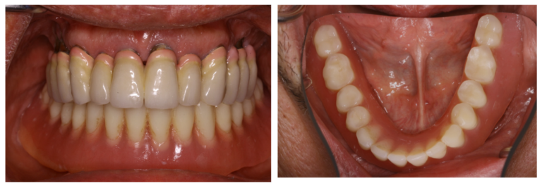
Existing mandibular overdenture in frontal and occlusal views. Its poor retention prompted fixed rehabilitation; the existing occlusal scheme provided a reference for planning. Decision and rationale. The authors retained the existing occlusal scheme as a planning reference while addressing the overdenture’s poor retention.
Step 2 of 8 · Digital imaging
CBCT anatomy

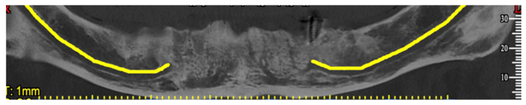
CBCT panoramic reconstruction with the mandibular nerve paths marked. Cross-sectional assessment and the full CBCT dataset remain necessary; this overview is not a stand-alone safe-distance prescription. Decision and rationale. The authors combined CBCT and surface-scan records to relate the restorative reference to the mandibular anatomy.
Step 3 of 8 · Clinical records · digital plan and CAD
From clinical records to the digital plan

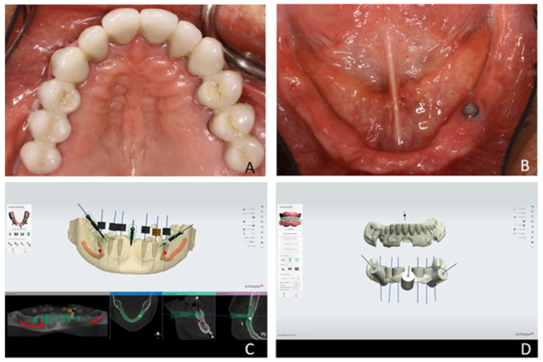
A–B establish the opposing restoration and mandibular tissues. C shows implant, fixation-pin and sleeve planning; D shows the two-piece guide CAD. The existing denture supplies the prosthetic reference. Decision and rationale. The two-piece design used an occlusal overlay based on the existing denture to help orient the surgical component.
Step 4 of 8 · Manufactured guide
The manufactured two-piece guide

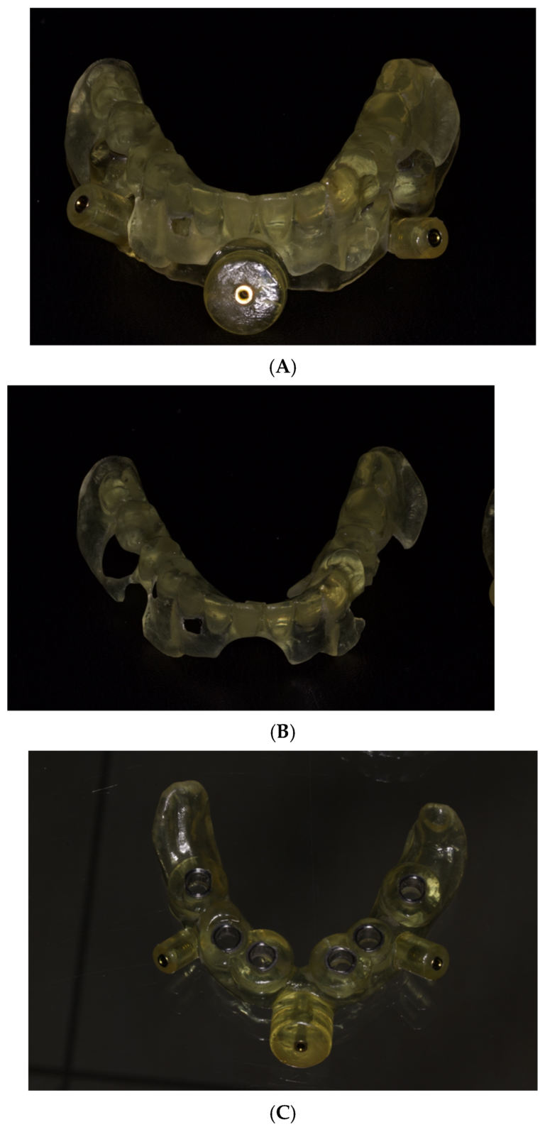
A shows the assembled guide, B its denture-shaped occlusal component, and C the surgical component with metal sleeves. The components transfer the planned seating relationship and fixation to the clinical stage. Decision and rationale. The occlusal component provided positioning; the sleeved component used mucosal support and fixation pins. Detailed validated print, wash, cure and sterilization records are not supplied.
Step 5 of 8 · Clinical guide use · provisionalization
Clinical transfer and immediate provisionalization

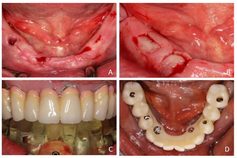
A–B show site marking and the authors’ H-shaped access incisions. C shows guide seating in intercuspation; D shows the provisional positioned for intraoral connection. Drilling through the sleeves is described in the paper, but is not photographed here. Decision and rationale. The authors chose the H-shaped access to see the underlying bone while retaining guide support. This is their case-specific approach, not a universal incision recommendation.
Step 6 of 8 · Provisional delivery · later digital verification
Provisional restoration to prosthetic verification

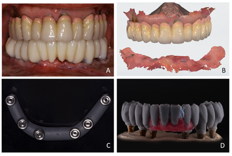
A shows the delivered provisional. B records the later digital articulation; C–D show the printed verification jig and trial prosthesis used before definitive manufacture. These panels span more than one treatment visit. Decision and rationale. Bite registration carried the provisional reference into digital articulation. The jig and trial restoration were used to check fit, occlusion and esthetics before definitive manufacture.
Step 7 of 8 · Clinical restorative assessment
Tissues and abutments before the final restoration

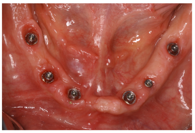
Occlusal view of the mandibular tissues and multi-unit abutments in the restorative phase. The publication does not assign this photograph a dated postoperative interval. Decision and rationale. This photograph documents the restorative-stage tissues and abutments. It cannot establish a timed healing or long-term success claim.
Step 8 of 8 · Definitive restoration · delivery
Definitive restoration and delivery
Previous: step 7Final step

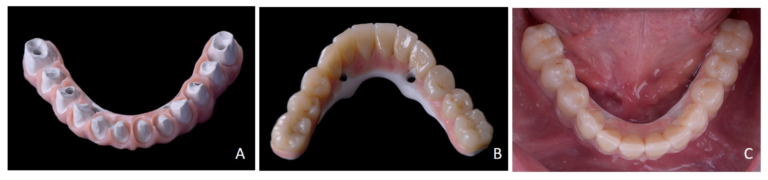
A–B show the definitive PEEK-framework restoration with zirconia crowns; C shows it delivered. This is a final-delivery image, not a documented long-term follow-up result. Decision and rationale. The reported sequence ends with delivery of the definitive restoration. A delivery photograph does not establish later implant or prosthesis survival.
What does the clinical evidence show?
In Varga and colleagues’ randomized trial, 207 implants were placed in 101 partially edentulous patients. Mean angular deviation was 7.03° for freehand and 3.04° for fully guided placement; mean apical global deviation was 2.43 and 1.59 mm, respectively. The coronal comparison was not statistically significant. These are study-specific results, not guaranteed tolerances for a product or patient.
Accuracy also does not automatically establish a biological advantage. A 2024 three-year randomized trial involving 60 implants in 18 patients found no significant between-group difference in marginal bone-level change. Different operator experience was built into its guided and freehand groups, so it should not be read as an isolated test of guidance alone.
A practical example comes from Lin and colleagues’ prospective study. Of 50 implants in 21 patients, seven molar implants required freehand insertion because of limited mouth opening. Accuracy analysis covered 43 fully guided implants, with mean global deviations of 0.78 mm at the platform and 1.28 mm at the apex. Two implants in one patient were removed because of pain during healing. The study illustrates both the potential and the limits of a digital workflow; it does not establish a guaranteed accuracy threshold or the outcome of a different clinical indication.
What should be recorded after surgery?
Record whether the planned guidance was completed, any change of approach, implant stability and the chosen loading pathway. Keep deviations from the plan distinct from complications and from longer-term clinical outcomes.
The 2026 ADA/AAOMR recommendations favour two-dimensional intraoral imaging for baseline and follow-up peri-implant bone assessment, with CBCT for appropriate complication-related questions. A postoperative CBCT taken for an accuracy study should not become an automatic examination for every asymptomatic implant patient.
Dynamic navigation is another method of transferring a plan, with a different registration and tracking workflow. A 2026 randomized comparison of one dynamic and one static system, involving 70 implants in 45 patients, found no significant accuracy difference. New navigation, AI and robotic tools should therefore be judged by their specific evidence and instructions rather than described collectively as safer or more precise than clinicians.
What should the dentist and laboratory do next?
The answer to the opening question is a chain of verified decisions. The following actions are DDS teaching interpretation of the evidence and instructions discussed above.
For the dentist
- Plan for residual deviation. Clinical studies show that guidance still differs from the virtual plan. Examine the complete implant and osteotomy envelope and retain the appropriate anatomical allowance; a study mean is not the tolerance for your next patient. Varga et al.
- Inspect registration before measuring. Dental references and restoration artefacts can affect alignment. Check separated surfaces and cross-sections, and resolve discrepancies before planning further. Registration study
- Check the entire instrument assembly. Posterior access prevented some fully guided insertions in Lin et al. Test mouth opening and access, and plan an alternative; the study does not establish a universal minimum opening. Lin et al.
- Keep loading conditional. Confirm actual primary stability and the restorative plan before immediate loading. Correct guide seating alone does not establish eligibility. ITI loading guidance
For the laboratory
- Match the complete system. Reconcile the implant, software library, sleeve, drill/handle combination and exported protocol with the surgeon. A brand name in a library is insufficient. exoplan Library Finder
- Check support at each surgical stage. Specify which structures remain after extractions or other steps. Model-study findings do not justify a universal three- or four-tooth support rule. El Kholy et al.
- Follow the indicated processing chain. Use the material’s compatible print, wash, cure and cleaning instructions; inspect the guide for damage. Printer layer height is not clinical placement accuracy. Example resin IFU
- Verify the manufactured guide. Assess seating, stability, sleeve retention and irrigation access with the clinical team. A successful CAD export is not a completed fit check. Example surgical-system guide
DDS brings these decisions together to make digital planning teachable and usable. Explore DDS digital-dentistry education for further learning; individual treatment decisions remain the responsibility of the treating clinician.

WHERE DIGITAL MEETS CLINICAL
DIGITAL DENTISTRY SCHOOLOGY
Perio-Implantologist
International Digital Dentistry Speaker
Digital Occlusion Consultant
Founder of DDS
Founder of Occlusa AI Platform
 h.sharshar@ddschoology.com
Written by Dr Haitham Sharshar
Dr. Haitham Sharshar is an international digital dentistry speaker, educator, and digital occlusion consultant based in Cairo, Egypt. His work focuses on functional digital dentistry, CAD/CAM, implantology, jaw-motion analysis, and the integration of digital diagnostics into clinical treatment planning.
As Founder and Scientific Coordinator of Digital Dentistry Schoology (DDS), he has trained more than 3,270 dentists and dental technicians through university programs, international conferences, and hands-on courses. His teaching connects patient-specific diagnostic records with digital design and clinical workflows, helping clinicians and technicians understand how function and occlusion inform restorative planning.
Dr. Sharshar is a certified trainer for zebris JMA-Optic+ jaw-motion analysis and MyoWise dental EMG. His educational and consulting work brings together patient diagnostics, jaw-motion records, muscle-activity data, digital occlusion, and AI-supported workflows.
He is Founder and Clinical Director of Occlusa, an AI-supported platform for organizing clinical information and supporting clinician-led review and treatment planning. He also owns HS Dental Clinic in Cairo, where his clinical focus includes full-mouth digital rehabilitation and smile design.
His speaking and training topics include functional digital dentistry, digital occlusion, jaw-motion analysis, CAD/CAM workflows, digital implantology, and the practical integration of AI-supported tools into dental education and clinical practice.
Happy to collaborate on spreading digital dentistry.