
Computational Biomechanics: What Can Dental FEA Predict?
Introduction
Does a lower-stress implant model mean a restoration will last longer? Finite element analysis (FEA) can compare mechanical responses under defined assumptions, but a stress map is not a measurement of clinical survival. The useful question is what was modeled, how it was checked, and whether the evidence supports the dental decision being considered.
Patient-derived anatomy can make a model more relevant to a particular question without making every material property, contact condition or chewing load patient-specific. This article follows that distinction from model construction to laboratory comparison and clinical observation.
Learning objectives
After reading, you should be able to:
- Explain how geometry, material properties, interfaces and loading assumptions shape a dental finite element analysis.
- Distinguish numerical verification, calibration and validation against independent experimental data.
- Interpret predicted stress, measured laboratory behavior and observed patient outcomes as different forms of evidence.
- Identify the applicability and evidence checks needed before using a model to inform a dental decision.
Clinical Overview
Computational biomechanics in dental applications primarily involves simulating physical interactions within the body using computational tools. Digital dentistry, enhanced by the use of Finite Element Analysis (FEA), offers a scientific approach to model complex mechanical behavior in dental restorations and implantology.
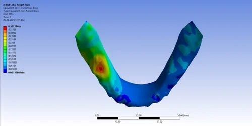
Finite Element Analysis (FEA) in Prosthodontics & Implantology
FEA divides a representation of a restoration, implant or supporting tissues into smaller elements and estimates their mechanical response to specified loads and constraints. It can help compare designs; the predicted response remains conditional on the geometry, material properties and interfaces represented.
Applications of FEA in Prosthodontics and Implantology:
The applications below describe questions that a model can investigate. They are not evidence that every modeled improvement produces a corresponding patient benefit.
1. Implant Design and Optimization
FEA can compare how implant geometry or assigned material properties change the modeled mechanical response. An apparently favorable design still needs evidence appropriate to its intended use; reduced simulated stress alone does not establish greater stability or longevity in patients.
2. Stress Distribution in Implant Systems
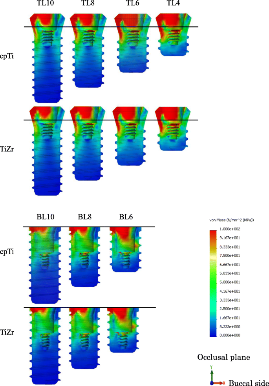
Stress maps show where the chosen model concentrates mechanical loading. Read the quantity, units, loading direction and color scale before comparing plots. A high-stress region is not, by itself, a diagnosis of future bone resorption or implant failure.
3. Prosthesis Design
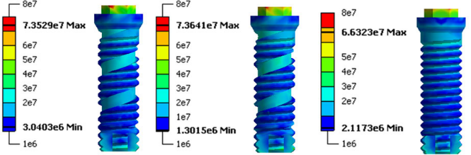
For crowns, bridges and other prostheses, a model can identify regions worth investigating under specified loads. Estimates of stress or deformation should be distinguished from experimentally measured fracture, wear and fatigue, and from clinical service life.
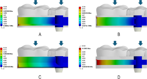
4. Assessment of Bone-Implant Interface
The assumed bone–implant interface changes load transfer. A fully bonded interface and a contact interface represent different mechanical conditions; neither assumption alone demonstrates that healing has occurred in a patient.
- Experimental example: Omori and colleagues (2015) compared contact and fixation representations with an artificial-mandible experiment. Their work illustrates why the chosen interface and the quantity being tested must be stated.
5. Simulating Surgical Procedures
A simulation of drilling or cutting would need assumptions and experimental comparisons specific to that process. A static implant-loading analysis does not identify the safest surgical approach or establish freedom from tissue injury.
6. Material Selection
Material comparisons are conditional on the properties and failure criteria assigned to each material. A stress comparison is not enough to select titanium, zirconia or a ceramic for an individual patient; processing, experimental performance and relevant clinical evidence remain separate considerations.
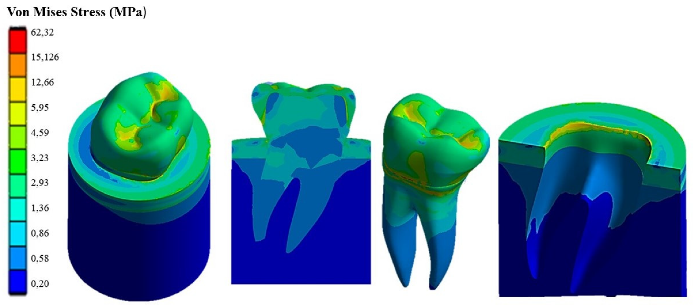
7. Evaluation of Occlusal Forces
Loading magnitude, direction, position and repetition influence the mechanical question being tested. A static force applied at one point is not a complete representation of a patient’s chewing or grinding, and it cannot by itself establish resistance to wear or clinical failure.
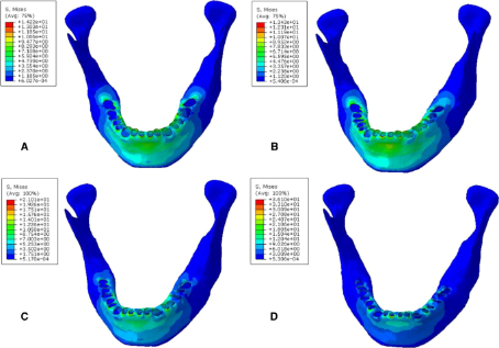
8. Bone Remodeling Prediction
Bone-remodeling models require a relationship between mechanical stimulus and biological change in addition to a stress calculation. Compare their predictions with observed bone changes rather than assuming that a favorable contour plot prevents bone loss.
9. Customization of Implants for Individual Patients
Patient-specific geometry can help explore an individual anatomical question. It does not automatically supply that patient’s true tissue properties, interface conditions or future loading, nor guarantee a better treatment outcome.
10. Fatigue and Durability Testing
Fatigue analysis addresses repeated loading through an explicit fatigue model and supporting material data. Do not translate a static stress result or simulated cycle count directly into years of clinical service.
Challenges and Limitations:
· Modeling Complexity Include the detail needed for the stated mechanical question. Simplification is often necessary; its effect on the relevant result needs evaluation. A more elaborate model is not automatically more accurate.
· Material Properties Accurately modeling the material properties of dental materials and bone is crucial for reliable results. However, the variability in material properties (e.g., bone density and implant surface coatings) across different individuals makes it difficult to create universally accurate simulations. The assumptions made about these materials, such as uniformity or ideal conditions, may not always reflect real-world variability.
· Load and Stress Simulations Real-world forces acting on implants and prostheses are dynamic and multifactorial, involving chewing, grinding, and other movements. Simulating these forces using FEA can be challenging due to the unpredictability of how loads vary across different situations and patient behaviors. Often, static or simplified loading conditions are used, which may not reflect the full complexity of occlusal forces.
· Bone-Implant Interface Variability The interface between the implant and bone is critical for the success of dental implants, and its modeling in FEA can be problematic. The interaction between these two materials is influenced by various factors like bone quality, implant surface texture, and healing processes. Accurately representing these interactions in a finite element model is difficult, and errors in simulation can lead to misguided implant designs or treatment plans.
· Patient-Specific Variability While FEA has the potential to create patient-specific simulations, obtaining accurate and detailed data for individual patients (such as CT scans or MRI) is often resource-intensive. Additionally, slight anatomical variations in bone structure can lead to significant differences in implant behavior, making it hard to create universally applicable models for all patients.
· Time-Consuming Process Building accurate FEA models, conducting simulations, and analyzing results can be time-consuming, especially for complex systems. This process may require advanced software, powerful computing resources, and considerable expertise, which can limit its accessibility in clinical settings.
· Over-Reliance on Simulation FEA is a valuable tool, but it is based on certain assumptions and approximations that may not fully account for all real-world factors. Relying solely on simulation results without considering clinical evidence and patient-specific factors can lead to suboptimal treatment plans. It’s essential to balance FEA insights with clinical judgment and experience.
· Software and Hardware Limitations Available software and computing resources constrain what can be modeled. Numerical checks, including mesh-convergence assessment where relevant, address calculation error; faster hardware or a denser mesh alone does not establish biological validity.
· Cost and Accessibility Advanced FEA tools and the required computational resources can be expensive, which may limit access to these technologies, particularly in smaller dental practices or regions with fewer resources. The initial investment in software, hardware, and training can be a barrier for some professionals, despite the long-term benefits FEA may offer.
· Comparability and Credibility Different geometry, loads, material laws and interfaces can make study results difficult to compare. The FDA’s November 2023 guidance offers a risk-informed credibility framework for first-principles models in medical-device submissions. It is nonbinding guidance, not a dental clinical trial or a universal treatment protocol.
What Have Primary Studies Actually Tested?
Laboratory comparison: similar trends can conceal numerical differences
Omori et al. (2015) compared three artificial-mandible models with FEA under 100-N vertical loading. Displacement trends were similar, but the models predicted smaller absolute displacements and stress reproducibility was poorer. Agreement in the direction of a response is therefore different from accurate prediction of its magnitude. These were laboratory findings, not patient survival results.
Clinical comparison: stress reduction and observed bone loss are different outcomes
Ormianer et al. (2012) combined FEA with retrospective records of first-molar implant restorations from three practices. The published abstract reports reduced simulated stress with increasing implant diameter, while only the widest clinical group had significantly lower bone loss than the other groups. This observational comparison does not prove that selecting treatment by FEA improves survival or establish a diameter suitable for every patient.
What Should Be Checked Before Using a Model?
- Define the decision: State the question, the model’s role and the consequence of a wrong prediction. The FDA framework distinguishes numerical verification from validation against independent empirical data; fitting a model to calibration data is not independent validation.
- Check applicability: Identify which anatomy, materials, interfaces and loading conditions are represented. Ask whether the experimental comparison tests the same quantity and conditions needed for the intended dental use.
How Far Can the Evidence Be Taken?
Research Findings:
- Laboratory behavior: Akça et al. (2002) compared strain-gauge measurements and FEA for implant-supported prostheses under static loading. The abstract reports compatible loading-pattern conclusions despite higher experimental strain values. This supports a bounded mechanical comparison, not a claim that FEA-guided restorations last longer or have fewer complications.
- Observed bone change: Assoratgoon et al. (2025) studied 12 participants with 22 posterior implants, relating FEA estimates to longitudinal bone-volume changes. Their abstract reports an association between strain energy density and buccal bone-volume loss. An association in this small cohort is not a trial showing better outcomes from FEA-guided care, and its imaging schedule is not a routine follow-up recommendation.
How Should New Digital Methods Be Judged?
- Machine learning: An AI label does not establish that a model accurately represents an individual’s chewing or predicts treatment success. Identify the actual method and the evidence for its stated use. The cited FDA guidance does not cover standalone AI/ML models.
- Physical prototypes: A printed model can support a defined experiment, but anatomical resemblance is not proof that its material properties and mechanical behavior reproduce living tissues. Treat prototype testing and patient outcomes as separate evidence.
What Would Support a Claim of Better Clinical Outcomes?
- Survival: Look for observed patient follow-up with a defined restoration or implant outcome, a clear denominator and a relevant comparator. A simulated reduction in stress does not supply these data.
- Complications: Distinguish recorded biological or technical complications from a modeled mechanical response. A clinician’s endorsement, even when attributable, cannot replace an appropriately designed comparative study.
Tips & Tricks: Read the Model Before Applying the Result
For the dentist, identify the clinical question and keep predicted stress, measured laboratory behavior and observed patient outcomes separate. For the laboratory or modeling team, state geometry, materials, interfaces and loads, then explain what was tested and where predictions remain uncertain. Use FEA to investigate a defined mechanical question; do not promise longer survival or fewer complications from a stress map alone.
References (5)
- U.S. Food and Drug Administration. Assessing the Credibility of Computational Modeling and Simulation in Medical Device Submissions. November 2023. Nonbinding guidance.
- Omori M, Sato Y, Kitagawa N, Shimura Y, Ito M. A biomechanical investigation of mandibular molar implants: reproducibility and validity of a finite element analysis model. International Journal of Implant Dentistry. 2015;1:10. doi:10.1186/s40729-015-0011-5.
- Akça K, Cehreli MC, Iplikçioglu H. A comparison of three-dimensional finite element stress analysis with in vitro strain gauge measurements on dental implants. International Journal of Prosthodontics. 2002;15(2):115–121. PMID:11951799. Abstract.
- Ormianer Z, Palti A, Demiralp B, Heller G, Lewinstein I, Khayat PG. Implant-supported first molar restorations: correlation of finite element analysis with clinical outcomes. International Journal of Oral & Maxillofacial Implants. 2012;27(1):e1–e12. PMID:22299100. Abstract.
- Assoratgoon I, Wan B, Tenkumo T, et al. Three-dimensional in vivo and finite element analyses of peri-implant bone remodeling after superstructure placement. Journal of Prosthetic Dentistry. 2025;133(6):1535–1544. doi:10.1016/j.prosdent.2025.01.015. Abstract.
About Dr. Haitham Sharshar



Dr. Haitham Sharshar is an international digital dentistry speaker, educator, and digital occlusion consultant based in Cairo, Egypt. His work focuses on functional digital dentistry, CAD/CAM, implantology, jaw-motion analysis, and the integration of digital diagnostics into clinical treatment planning.
As Founder and Scientific Coordinator of Digital Dentistry Schoology (DDS), he has trained more than 3,270 dentists and dental technicians through university programs, international conferences, and hands-on courses. His teaching connects patient-specific diagnostic records with digital design and clinical workflows, helping clinicians and technicians understand how function and occlusion inform restorative planning.
Dr. Sharshar is a certified trainer for zebris JMA-Optic+ jaw-motion analysis and MyoWise dental EMG. His educational and consulting work brings together patient diagnostics, jaw-motion records, muscle-activity data, digital occlusion, and AI-supported workflows.
He is Founder and Clinical Director of Occlusa, an AI-supported platform for organizing clinical information and supporting clinician-led review and treatment planning. He also owns HS Dental Clinic in Cairo, where his clinical focus includes full-mouth digital rehabilitation and smile design.
His speaking and training topics include functional digital dentistry, digital occlusion, jaw-motion analysis, CAD/CAM workflows, digital implantology, and the practical integration of AI-supported tools into dental education and clinical practice.
WHERE DIGITAL MEETS CLINICAL
Happy to collaborate on spreading digital dentistry.
h.sharshar@ddschoology.com