
Robot-Assisted Endodontics: What Is Automated?
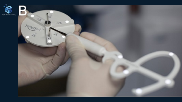
Can a robot complete a difficult root-canal treatment, or does it perform one carefully planned part? Published clinical reports describe robotic assistance for selected canal-access, bone-removal and root-end resection tasks. The clinician still selects the treatment, plans and supervises the intervention, and performs other essential stages. These reports demonstrate feasibility in particular patients; they do not establish fully autonomous root-canal treatment or better long-term outcomes. Liu 2024; Huang 2025; Wan 2025.
For the dentist, the useful question is therefore specific: which movement can this system assist, what must happen before it moves, and who completes the treatment afterward? For the digital planning or laboratory team, the corresponding question is whether the records and patient-specific accessories faithfully support that planned task.
What does “autonomous” mean in these reports?
Autonomy describes a task within a treatment. In the Wan report, the arm followed a preplanned path to enter, cut bone and resect the mesiobuccal root end, then withdraw. An endodontic specialist controlled the sequence with a foot pedal and monitored the display. The other buccal root and the remaining microsurgical treatment required manual work. That division of responsibility is more informative than calling the whole operation autonomous. Wan, surgical procedure.
Haptic guidance is a different form of assistance. Isufi and colleagues reported use of Yomi for upper-left first- and second-premolar endodontic surgery, with tactile, auditory and visual guidance during osteotomy and root-end resection. This case should not be recast as an arm independently completing the surgery. Isufi 2024.

Read the learning map
- Clinical question. Which task is appropriate? Assess the anatomy and alternatives.
- Matched imaging + records. Connect radiographic anatomy with the surface model.
- Registration + verification. Check the record-to-patient link using system-specific instructions.
- Bounded robotic task. Wan: supervised MB entry, osteotomy, resection and exit.
- Clinician completion. Wan: DB-root surgery and remaining microsurgery were manual.
- Patient outcome. Review symptoms and imaging at the reported follow-up.
Keep three questions separate: the plan asks what was intended; the task asks what was executed, by whom and with what measured error; the patient asks what was observed in symptoms, imaging and follow-up. MB means mesiobuccal; DB means distobuccal.
DDS educational synthesis, not a validated protocol. Wan et al. (2025).
Keep evidence levels separate. A clinical case describes observed care in an individual patient; a model study tests technical performance; laboratory or ex-vivo work does not establish patient benefit. Haptic guidance and autonomous movement describe different operator roles.
The same sequence in words: establish the clinical indication; combine and inspect the records; define the task and access constraints; register the patient and instruments; supervise the assisted movement; complete treatment and assess healing. This is a reading framework for the reports below, not a substitute for system-specific training or a treatment protocol.
How did a real maxillary second-molar case proceed?
Evidence added for this 4 October 2026 update: Wan and colleagues’ report was published on 27 October 2025, after the original DDS article. It documents one previously treated left maxillary second molar with persistent symptoms and periapical radiolucencies at the buccal roots. The report is useful because it follows the same patient from clinical assessment through the digital plan, printed registration accessories, surgery and six-month review. It also shows where robotic access stopped being practical. Wan 2025.
Preview limits. These images provide an educational overview. Small anatomical details, measurements and navigation readouts may not be readable in the previews; use the full-size image and source paper to inspect them.
Step 1 of 6 · Clinical assessment
What made access difficult?
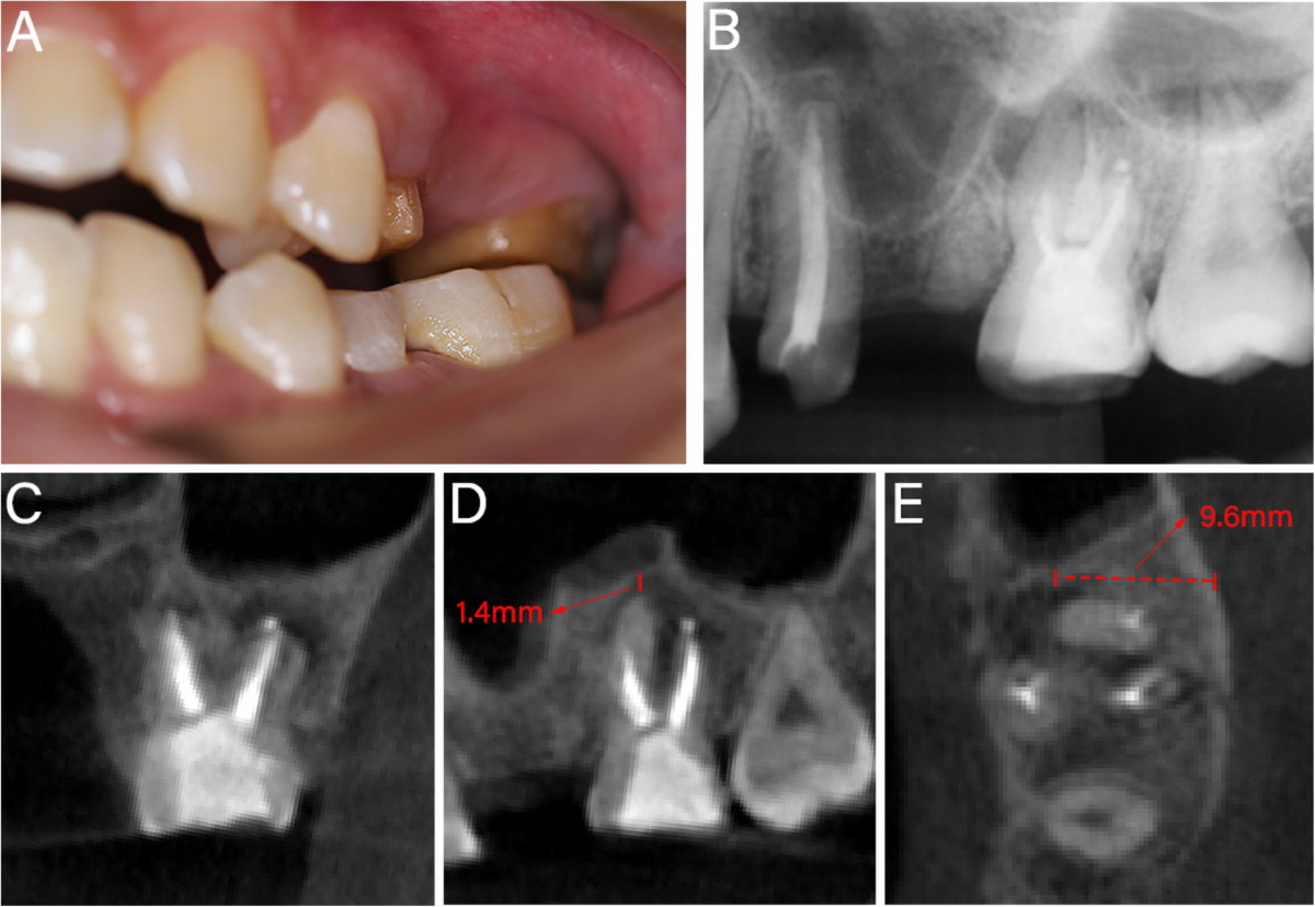
The mesiobuccal (MB) apex lay close to the maxillary sinus, and the buccal cortical plate was intact. The source labels a minimum MB-apex-to-sinus distance of 1.4 mm and a 9.6 mm distance from the MB root’s lingual surface to the buccal cortex. These describe this patient’s anatomy and access depth, not the robot’s positioning error.
The treating team considered the limitations of retreatment and simulated surgical access before choosing assistance. This selected case does not make robotics the default treatment for a second molar.

Figure 1A–EPreoperative clinical photograph, periapical radiograph and CBCT sections from the reported left maxillary second-molar case. The original annotations show a 1.4 mm MB-apex-to-sinus-floor distance and a 9.6 mm lingual-root-surface-to-buccal-cortex span. Case source and image changes. Step 2 of 6 · Digital planning
How were the records combined?
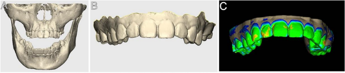
CBCT data in DICOM format and an intraoral surface scan in STL format were combined in DentalNavi to create the patient-specific model. The case used the YakeBot robotic system. These manufacturer links identify the platform and software; the case report is the source for what was performed.
DDS teaching point: examine the agreement between the surface records and the radiographic anatomy before relying on a proposed path. A convincing combined model is not itself a measured accuracy result.

Figure 2A–CCBCT jaw data (A), an intraoral surface scan (B) and their fitted digital model (C) supported this patient’s surgical planning. Case source and image changes. Step 3 of 6 · Digital design
Which root could the robot reach?
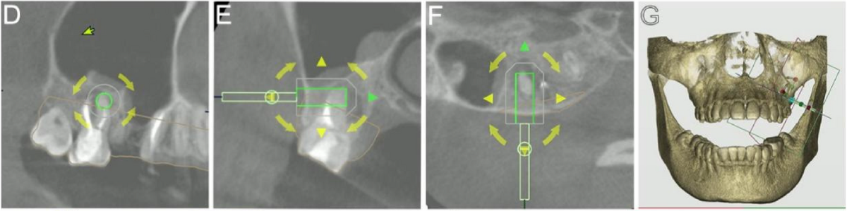
The plan targeted 3 mm of MB root-end resection with a trephine described as 3.5 mm in diameter and 10 mm long. The path was designed around the sinus. Limited cheek retraction prevented the same robotic approach to the distobuccal (DB) root, so that root was treated freehand using the MB site as a reference.
Keep the quantities separate: resection length, instrument dimensions and anatomical distances answer different questions. None is a transferable safety margin or a universal device setting.

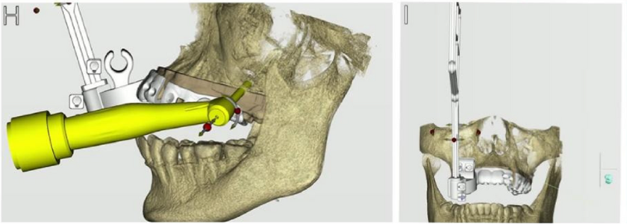
Figure 2D–GSectional and three-dimensional planning views show the proposed approach for 3 mm of mesiobuccal (MB) root-end resection while avoiding the maxillary sinus. The distobuccal (DB) root was planned for freehand treatment because cheek access was limited. Case source and image changes. 
Figure 2H–IThe virtual trephine approach (H) and digital patient-specific accessory and optical-marker arrangement (I). The selected trephine was 3.5 mm in diameter and 10 mm long. Case source and image changes. Previous: recordsNext: printed accessoryView source Figure 2
Step 4 of 6 · Manufactured accessory
What was actually 3D printed?
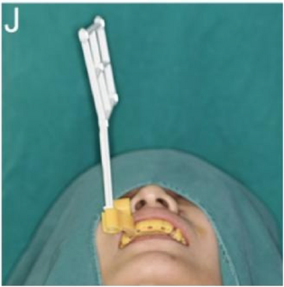
The authors report 3D printing patient-specific surgical accessories. The digital accessory and the physical intraoral component with its optical marker appear together in Figure 2I–J. The marker was oriented parallel to the patient’s sagittal plane to accommodate the posterior surgical position.
The report shows the manufactured component in use; it does not provide a printer-process photograph or a reproducible resin, print and post-processing protocol. A laboratory should obtain the exact compatible manufacturing and device instructions rather than infer them from the photograph.

Figure 2JFinished patient-specific accessory and optical marker fitted for this case. The authors report 3D printing; the printing process is not shown. Case source and image changes. Step 5 of 6 · Clinical delivery
Where did the surgeon take over?
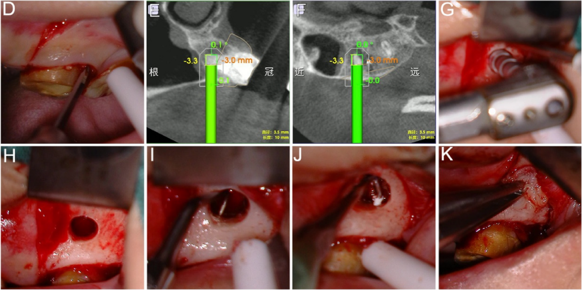
After calibration and registration, the supervised robotic sequence performed MB entry, osteotomy, root-end resection and withdrawal. Its reported 80 seconds covered that sequence only. The surgeon then enlarged the cavity, resected the DB root end freehand, and completed curettage, ultrasonic root-end preparation and filling. Concentrated growth-factor membranes were also placed before closure.
Important limitation: the apical foramen of the second mesiobuccal (MB2) canal was not found. The report describes no observed sinus-floor injury, but this single observation cannot establish that the system prevents such injury. The robotic movement did not remove the need for microsurgical skill or intraoperative assessment.

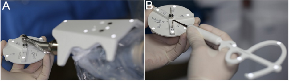
Figure 3A–BSystem setup included robotic-arm, trephine and probe calibration. These source panels show calibration equipment, not the manufacture of the patient-specific accessory. Case source and image changes. 
Figure 3D–KSelected operative panels: flap exposure (D); navigation displays during the supervised robotic MB step (E–F); manual DB-root resection and the resulting field (G–H); root-end preparation and filling (I–J); and CGF membrane placement (K). The source text places registration after flap exposure and before the robotic step; registration is not pictured here. Case source and image changes. 
Figure 4A–BImmediate postoperative photograph after suturing (A) and periapical radiograph (B) from the same reported case. Case source and image changes. Previous: manufactureNext: observed follow-upView source Figure 3
Step 6 of 6 · Observed outcome
What did six-month review show?
The sequence includes immediate postoperative assessment, one-week review and suture removal, then six-month clinical and radiographic follow-up. At six months the authors reported satisfactory clinical findings and recovery of periapical bone density.
This is a short-term observation after combined treatment in one patient. It cannot isolate a robotic healing effect from the manual surgery, root-end treatment or membrane placement. It is not a comparative success rate, proof of complete radiographic healing or a long-term tooth-survival result.

Figure 4C–FOne-week review and suture removal (C–D), followed by six-month clinical and radiographic review (E–F). The authors report satisfactory clinical status and recovery of periapical bone density at six months. Case source and image changes.
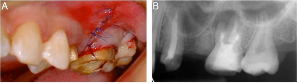
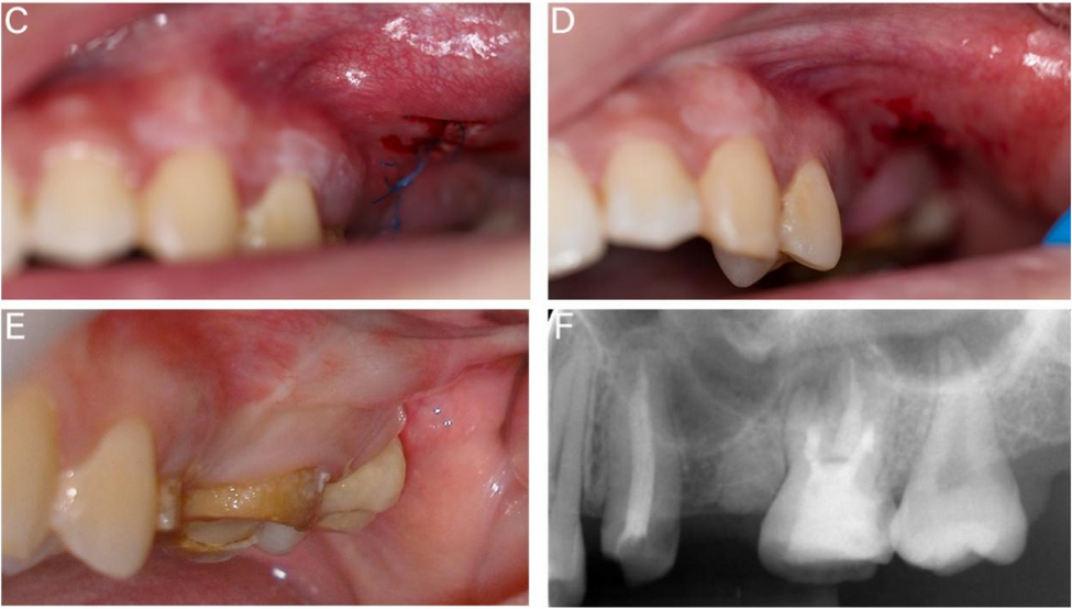
The source identifies this tooth as the left maxillary second molar and uses US tooth number “#15.” That number must not be interpreted as FDI 15. The anatomical name is used throughout this explanation to avoid confusion.
What other endodontic tasks have been reported?
Microsurgical access and resection. Liu and colleagues described robot-directed osteotomy and root-end resection for a previously treated mandibular left first molar. The clinician subsequently examined the resected surface and carried out root-end preparation and filling under a microscope. The accessible abstract supports this division of work; it does not establish comparative bone preservation or a measured submillimeter error for this patient. Liu 2024.
Locating a calcified canal. Huang and colleagues reported planned robotic access to a left maxillary central incisor with pulp canal obliteration, pulp necrosis and symptomatic apical periodontitis. Infection control and root filling followed, with symptom relief after the combined treatment. The abstract does not attribute those later stages to the robot or establish a general outcome advantage. Huang 2025.
Access to an extruded fractured file. In Fu and colleagues’ case, the robot created an initial 3 mm round bone window. The surgeon enlarged it freehand to an approximately 4.5 mm keyhole and retrieved the fragment manually; root resection was avoided. The cortical plate had been intact before surgery, so the case cannot be described as preserving all cortical bone. Fu 2025.
Fu reported about 30 minutes of preparation and an approximately nine-minute interval covering creation of the window and enabling operator retrieval. That is neither isolated robotic drilling time nor total treatment time. Baseline imaging showed no periapical radiolucency; the nine-month radiographic finding concerned healing of the surgical bone-window site. These details change the clinical interpretation, even though the procedure is technically interesting. Fu, procedure and follow-up.
The common lesson is to name the completed task precisely. “The robot helped reach the target” says less about disinfection, obturation, restoration and long-term retention than “the robot completed the treatment” would imply.
Does greater accuracy mean faster or better treatment?
Chen and colleagues compared robotic assistance, dynamic navigation and static navigation in 72 teeth in standardized jaw models, with 24 teeth per group. Robotics produced smaller platform, angular and resection-angular deviations than both navigation groups; its resection-length deviation was smaller than dynamic navigation. There was no freehand group. Chen 2024.
The time result needs equal attention: static navigation had the shortest measured interval, followed by robotics, then dynamic navigation. Timing ran from foot-pedal activation until the bur reached the target depth. It did not measure scanning, planning, accessory production, setup or the whole appointment. Chen, methods and results.
For an equipment discussion, request the complete workflow and the exact outcome metric. Keep setup time separate from cutting time, and ask whether the comparison involved models or patients. An accuracy advantage is worth investigating without turning it into a patient-benefit promise.
Are microrobots already cleaning patients’ canals?
Babeer and colleagues studied magnetically controlled nanoparticle microswarms for biofilm disruption and retrieval, alongside a platform using 3D-micromolded soft helicoids. This was laboratory and ex-vivo proof-of-concept work, not a patient trial demonstrating better root-canal success. The platforms should not be described as clinically established autonomous canal-cleaning treatments. Babeer 2022.
Earlier engineering work also requires careful labels. Dong and colleagues’ 2007 paper proposed a miniature endodontic robot design and model. Its five motion axes and 20 × 20 × 28 mm envelope were design requirements; integrated sensor/actuator development and fabrication remained future work. That is useful development history, not evidence of a validated robot completing treatment in a patient. Dong 2007, original paper.
The next clinically meaningful evidence would connect technical performance to safe use, practical setup and patient outcomes. The reports summarized here are selected examples, not a systematic review of every study available in 2026.
What should the dentist and digital team do with this evidence?
DDS brings these reports together to make the division of work visible: the digital plan, the assisted movement and the clinical treatment must each be judged on their own evidence. The following are educational implications of the cited reports, not a new operative protocol.
For the dentist
- Define the intended task before selecting the technology. Calcified-canal access and root-end surgery solve different problems. Use the Huang and Wan reports to identify the task, then assess the patient’s indication and alternatives independently. A case report cannot select treatment for the next patient. Huang; Wan.
- Plan the manual part as carefully as the robotic part. Wan’s DB root needed freehand surgery and the MB2 foramen remained unidentified. Discuss physical access, supervision and the next clinical step before starting; a robotic trajectory does not replace a plan for incomplete access or unresolved anatomy. Wan.
- Explain the evidence without promising an outcome. Separate model accuracy, task duration and observed follow-up. Discuss uncertainty rather than promising less pain, faster total treatment or a higher survival rate from these selected studies. Chen; Wan.
For the digital planning or laboratory team
- Keep the records and manufactured accessory connected. Wan used a combined radiographic/surface model and a patient-specific registration component. Confirm the intended patient, anatomy, seating and marker orientation with the clinician; do not assume that a printable model alone establishes clinical suitability. Wan, acquisition and planning.
- Request the missing fabrication instructions. The paper does not supply a complete material, printing or post-processing protocol. Obtain compatible device and manufacturing instructions before production rather than copy dimensions or materials from an image. DDS’s dental 3D-printing education provides broader learning context; it is not certification to reproduce this robotic accessory.

Read the practical checkpoints
- Name the automated step. Ask exactly which movement was robotic and which treatment steps remained manual.
- Verify records and registration. Check the linked records, accessory fit and device-specific instructions before clinical use.
- Separate the measurements. A planning overlay, anatomical distance and achieved positioning error are different things.
- Plan the manual route. Assess physical access and retain clinician oversight and an appropriate manual fallback.
- Separate feasibility from benefit. One case does not prove superiority. A task timer does not measure the whole appointment.
- Follow the patient. Report observed symptoms and healing, with the follow-up interval and co-interventions.
DDS educational checkpoints, not a treatment protocol. Wan et al. (2025); Chen et al. (2024).
The answer to the opening question: these systems can assist a defined endodontic task within a clinician-led treatment. Their value should be assessed at that same level of detail, with accurate records, realistic access planning and follow-up that measures what actually happened.
Primary sources and reading limits
- Wan et al., BMC Oral Health, 2025;25:1686. Full case and Figures 1–4; single patient, six-month follow-up. Shared figure credit appears with the case.
- Liu et al., Journal of Endodontics, 2024;50:859–864. Clinical report; this summary is limited to the accessible abstract.
- Huang et al., Journal of Endodontics, 2025;51:1294–1300. Calcified-canal case; this summary is limited to the accessible abstract.
- Isufi et al., Journal of Endodontics, 2024;50:533–539.e1. Haptic-guided clinical report; accessible abstract.
- Fu et al., BMC Oral Health, 2025;25:8. Full report of robotic access and manual fractured-file retrieval. No figures from this paper are reproduced here.
- Chen et al., Journal of Endodontics, 2024;50:1448–1454. Model comparison; accessible abstract and publisher excerpts, not a patient-outcome study.
- Babeer et al., Journal of Dental Research, 2022;101:1009–1014. Laboratory/ex-vivo microrobotics research.
- Dong, Hong and Hasselgren, International Journal of Modern Engineering, 2007;8:26–34. Preliminary engineering design and model.
This educational synthesis supports critical reading and professional discussion. It does not establish a device-specific operative protocol, a new approved indication or a patient-specific treatment recommendation.

WHERE DIGITAL MEETS CLINICAL
DIGITAL DENTISTRY SCHOOLOGY
Perio-Implantologist
International Digital Dentistry Speaker
Digital Occlusion Consultant
Founder of DDS
Founder of Occlusa AI Platform
 h.sharshar@ddschoology.com
Written by Dr Haitham Sharshar
Dr. Haitham Sharshar is an international digital dentistry speaker, educator, and digital occlusion consultant based in Cairo, Egypt. His work focuses on functional digital dentistry, CAD/CAM, implantology, jaw-motion analysis, and the integration of digital diagnostics into clinical treatment planning.
As Founder and Scientific Coordinator of Digital Dentistry Schoology (DDS), he has trained more than 3,270 dentists and dental technicians through university programs, international conferences, and hands-on courses. His teaching connects patient-specific diagnostic records with digital design and clinical workflows, helping clinicians and technicians understand how function and occlusion inform restorative planning.
Dr. Sharshar is a certified trainer for zebris JMA-Optic+ jaw-motion analysis and MyoWise dental EMG. His educational and consulting work brings together patient diagnostics, jaw-motion records, muscle-activity data, digital occlusion, and AI-supported workflows.
He is Founder and Clinical Director of Occlusa, an AI-supported platform for organizing clinical information and supporting clinician-led review and treatment planning. He also owns HS Dental Clinic in Cairo, where his clinical focus includes full-mouth digital rehabilitation and smile design.
His speaking and training topics include functional digital dentistry, digital occlusion, jaw-motion analysis, CAD/CAM workflows, digital implantology, and the practical integration of AI-supported tools into dental education and clinical practice.
Happy to collaborate on spreading digital dentistry.